20/09/2021 – Fatigue strength diagrams
Development of fatigue strength diagrams for helical compression springs made of spring steel wire
At the end of 2020, the research project “IGF 19693 BR” at the TU Ilmenau in cooperation with the VDFI with the title “Renewal of the fatigue strength diagrams for cold-formed helical compression springs in DIN EN 13906-1 with a methodical and computational approach” was completed.
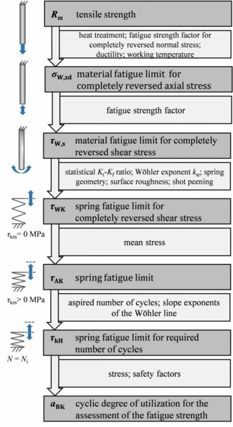
Fig. 1: Calculation of the fatigue strength [FKM20]. © TU Ilmenau
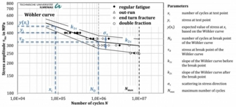
Fig. 2: Maximum likelihood evaluation of the results from the fatigue tests in the Wöhler diagram. © TU Ilmenau
A new method for the development of fatigue strength curves for compression springs was developed, which was then used to create fatigue strength diagrams for cylindrical helical compression springs for current materials and manufacturing processes.
Fatigue strengths contained in EN 13906-1 are out of date
The mathematical relationships and Goodman diagrams contained in the standard DIN EN 13906-1 [DIN13] form the essential basis for the design and calculation of cylindrical helical compression springs. They are not only used nationally, but throughout Europe and internationally in the spring industry and by spring users. However, the diagrams are over 50 years old and no longer reflect the current state of modern spring materials and springs made from them.
Since then, on the one hand, the wire materials have improved significantly (e.g. metallurgy, purity, drawing process, heat treatments, tensile strength, tolerances and uniformity) and, on the other hand, it is now known that the spring geometry (spring index, number of coils, etc.) process sequences and process parameters in the spring production (heat treatment, pre-setting, shot peening, etc.) as well as the operating conditions have a significant influence on the fatigue strength of the springs. According to the EN standard, these influencing factors are currently not taken into account in the spring design. For the users of the standard, this results in a certain uncertainty, as the graphs are partly very conservative (oil tempered wires), but partly also critical (stainless wires), which currently has to be compensated by cost-intensive fatigue tests. Small and medium-sized enterprises (SMEs) are absolutely dependent on meaningful and appropriate fatigue strength values and guidelines when designing their springs.
The main aim of the research project was therefore the development of a method for the renewal of these fatigue strength diagrams and, in particular, the creation of new fatigue strength diagrams. They should be as easy to use as the established Goodman diagrams.
Methodical approach
In order to limit the test effort for the numerous material and spring variants, a concept for the computational determination of the diagrams was developed. This is based on the one hand on a calculation algorithm from IGF 18495 BG [Rei17], and on the other hand on a very extensive fatigue database of results from earlier, publicly funded projects, which were carried out in cooperation with the VDFI. In order to expand the database for the new method in a targeted manner and to validate the new graphs, various experimental investigations were carried out in the research project.
The fatigue strength diagrams developed as part of the research project can be used directly for standard springs in standard applications as before. If required, the quality of the results for springs with properties (geometry, manufacture) that differ from the reference springs can be further improved using simple, analytical calculations. Fig. 1 clearly shows the mentioned algorithm to calculate the fatigue strength of compression springs.
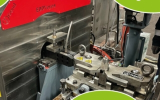
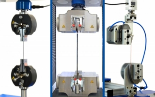
The fatigue tests up to a number of cycles N = 107on 42 cold-formed helical compression spring variants (reference springs with, among other things, identical spring index and number of spring coils) are of great importance for expanding the existing database. The spring design was based on tensile and torsion tests on the wire materials with wire diameters of 1mm to 10mm. The supplementary fatigue tests were carried out during the project period at the research center with three vibration machines and by members of the committee accompanying the project at room temperature in a non-corrosive environment with constant mean stress.
The entire database for helical compression springs consisted of 342 statistically evaluated fatigue strengths, which contain a multiple (several thousand) of individual breaks in springs. The large variety of test conditions, testing machines, manufacturing conditions and materials that are contained in this data are intended to ensure a broad applicability of the diagrams.
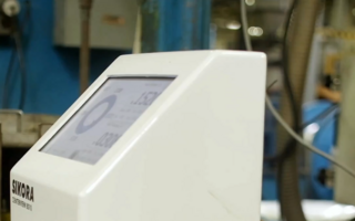
The cyclic tests were also supported by numerous other practical tests. This includes the recording of spring characteristics, hardness measurements, the determination of residual stresses on the basis of X-ray measurements on the spring surfaces and the measurement of the surface roughness. Fatigue fracture analyzes and contact angle measurements at the spring ends were also carried out in order to characterize fractures more precisely.
A special focus was on the statistical evaluation of the fatigue tests. After carefully weighing the advantages and disadvantages of various statistical evaluation methods, the maximum likelihood method was used [Spi79, Mül15]. The basis for the maximum likelihood evaluation of the results from the fatigue tests is the modeling of the bilinear Wöhler curve (S-N-curve) in a double logarithmic Wöhler diagram to determine the Wöhler curve parameters (fig. 2).
Calculation of new fatigue strengths
The computational renewal of fatigue strength curves was carried out using the draft guideline Computational Strength Verification for Springs and Spring Elements from IGF 18495 BG [Rei17] or the FKM guideline of the same name [FKM20] developed therein. The factors for determining the fatigue strengths with this calculation algorithm were checked and confirmed on the basis of the extensive fatigue tests and the statistically evaluated data points already contained in the guideline. An example is shown in Figure 3. The dispersion around the optimum (diagonal) is then taken into account using a safety concept.
The fatigue strength curves that have now been calculated were therefore reduced through the application of a two-stage safety concept also contained in the guideline in such a way that they can be assessed as conservative with regard to real test data. The permissible stresses read off in the diagrams are therefore lower than the tested stresses. A total of 24 diagrams were generated in two forms of representation (Goodman and Haigh diagram) for the cycles N = 106 and N = 107. The wire types are FDSiCr, VDSiCr, VDSiCrV, DH, 1.4310 and 1.4568 (example: “Diagram 8” in fig. 4).
The new strength diagrams were calculated for springs with the in fig. 4 stated parameters such as spring index, number of coils, surface roughness, residual stresses due to shot peening etc. In addition, a new method was developed to enable a mathematical transfer of the fatigue strengths from the diagrams to other, similar springs with different parameters. The design quality can be further increased in this way – but this is only necessary for critical designs. Known residual stresses as a result of pre-setting or as a result of shot peening treatment can be taken into account with higher accuracy with the aid of a mean stress shift. Statements about the static load capacity of the wires or springs can also be made on the basis of computationally determined torsional stress limits and the estimated stresses trough presetting. The permissible static stresses are shown as horizontal dashed lines in the new Goodman diagrams and serve as additional orientation for the user.
Conclusion and outlook
The results of the research project make a significant contribution to modern spring design and enable spring manufacturers (especially SMEs) to produce competitive and at the same time safe products. In addition, the results have been prepared in such a way that they are easy to use.
This means that the newly generated diagrams have the potential to be included in DIN EN 13906-1 in the future in order to replace the outdated diagrams currently printed there.
Therefore, support from spring designers and users from all over Europe is necessary. The VDFI and the authors want the new strength curves to be evaluated with many examples, before the update process for the EN standard can be started. Don´t hesitate to contact us in order to get more information.
Acknowledgements
This IGF Project 19693 BR of the Forschungsgesellschaft Stahlverformung e.V. (FSV) was supported via AiF within the programme for promoting the Industrial Collective Research (IGF) of the German Ministry of Economic Affairs and Energy (BMWi), based on a resolution of the German Parliament. The long version of the final report can be requested from FSV, Goldene Pforte 1, 58093 Hagen.
References
[DIN13] DIN EN 13906-1:2013-11, Zylindrische Schraubenfedern aus runden Drähten und Stäben - Berechnung und Konstruktion – Teil 1: Druckfedern, 2013
[FKM20] FKM Forschungskuratorium Maschinenbau e.V. (Hrsg.): Rechnerischer Festigkeitsnachweis für Federn und Federelemente – FKM Richtlinie für Federn und Federelemente. VDMA-Verlag, Frankfurt am Main, 2020
[Mül15] Müller, C.: Zur statistischen Auswertung experimenteller Wöhlerlinien. Universitätsbibliothek Clausthal, Clausthal-Zellerfeld, 2015
[Rei17] Reich, R.; Kletzin, U.; Oechsner, M.; Spies, A.; Klein, M.: Rechnerischer Festigkeitsnachweis für Federn und Federelemente – Abschlussbericht zum Forschungsvorhaben IGF 18495, Ilmenau, 2017
[Spi79] Spindel, L.; Haibach, E.: The method of maximum likelihood applied to the statistical analysis of fatigue data. International Journal of Fatigue, (Jahrgang 1) Heft 2, 1979, S. 81–88
The authors are Martin Petrich and Ulf Kletzin, TU Ilmenau.
Technische Universität Ilmenau
Institut für Maschinen- und Gerätekonstruktion
Fachgebiet Maschinenelemente
Max-Planck-Ring 12, 98693 Ilmenau, Germany
Contact person is Martin Petrich
Tel.: +49 3677 69-1865
martin.petrich@tu-ilmenau.de
stz-federn@tu-ilmenau.de
www.tu-ilmenau.de/maschinenelemente