16/09/2020 – Wire drawing
Modular drawing lines for large diameters
The long history of the company Kieselstein involves the successful manufacturing of plants for the processing of big diameter wire. This is used for cold heading parts, springs and similar components used amongst others in the automotive industry.
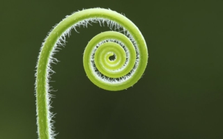
Fig. 1: Large diameter wire often challenges operators when it comes to handling. © Kieselstein
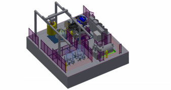
Fig. 2: Recent project of a single drawing block plant made by Kieselstein. © Kieselstein
Against this background and based on the fact that a higher level of safety and automation for wire producing plants is demanded, the company started reviewing its concept of the EH single block drawing plants. The following article explains the specialities and the modular concept.
Handling is a great issue in the drawing of big diameter wire (> 10mm). This includes:
– the positioning of the wire on the respective pay-off device
– the straightening of the wire for the pointing
– the pointing itself in preparation of the drawing process
– the feeding into the drawing plant
– the grabbing/clamping of the wire on the drawing capstan
– the transfer of the wire from the drawing capstan to the take-up device
– the unloading of the wire from the take-up device
– the packing and compacting of the wire coil
In principle the processing steps are similar to the ones with small diameter wire, however at larger diameters a manual handling is no longer possible and from an ergonomic point of view not recommended. The increasing demand for operational safety at wire drawing plants does the rest and, in the end, causes an increasing number of wire producers to review their existing plants regarding operational safety and ergonomics. Due to this development and based on the increased demand for solutions for the processing of big wire diameters the machine concept for single drawing machines was fundamentally revised. The following article will show the options for the single processing steps and will explain the appropriate module-based solutions.
Pay-off devices
Basically, there are two different types: Firstly, the horizontal pay-off, as shown in fig. 3 (left) and the vertical pay-off, also shown in fig. 3 (right). The difference between these two is mainly, as already suggested by the designation, the orientation of the rotation axis and the diameter range they are used for.
The horizontal pay-off is used in a range of wire diameters between 8mm and 50mm, whereby the range is also defined by the wire material or the tensile strength. The advantage of this pay-off device is in particular that the complete handling for the straightening (bending up) and advancing of the wire for the pointing and drawing-in process into the drawing plant is integrated into the pay-off. Besides a single station, also double pay-offs are widely used.
An alternative is the vertical pay-off. Compared to the horizontal pay-off, the vertical pay-off is used for wire with a lower tensile strength and a diameter smaller than 8 mm which increases the utilisation rate of the plant. A disadvantage of these pay-off devices is the impact of the coil height at the inlet into the drawing machine. From high wire coils the wire runs strongly downwards and may, at a small distance between the pay-off and the drawing machine, lead to damages at the surface. In addition, a vertical pay-off needs a separate unit for bending up and advancing which should be positioned depending on the height of the wire coil. For this purpose, appropriate lifting devices have to be available. On the other hand, the pay-off requires less space than a horizontal pay-off and can be loaded in different ways. It is possible to unwind directly from a stem which cannot be used with a horizontal pay-off. There it is necessary to bring the coils to a lateral position (eye to the side) and either load using a fork lifter or a C-hook. Even for the vertical pay-off, there are both single and double types. The appropriate type has to be chosen based on the targeted productivity of the entire plant and the pointing process selected.
Pointing of the wire
Basically, for the pointing of the wire at large diameters there are two main options – rolling and swaging. Also, with larger diameters often shaving is used for pointing the wire. This shows advantages mainly in the handling and in the quality of the point. However, it has to be kept in mind that not every wire material can be machined equally good, which can require several shaving steps before reaching the targeted diameter of the point.
An alternative for wire larger than 10mm is the so-called push pointer. The push pointer is located in the wire line. The wire without any point is led directly into the drawing block, is grabbed by a clamping device in front of the drawing die and is pushed into the drawing die. Picture 4 shows the design of the push pointer that can be installed even on existing drawing plants. By an automation concept which is explained later on, a fully automated process from the wire pay-off with bending-up, advancing and straightening, push-pointing/pointing and forwarding to the drawing block can be realized.
Drawing block
In the following the advantages of a horizontal drawing block are explained. At first, there are different sizes which mainly follow the necessary drawing force for the intended task. In the past special gears were commonly used. In the revised concept, those are replaced by standard slip-on gears which offer a much higher flexibility in the plant design. The selection of the appropriate gear leads to a higher efficiency and to a customised specification of the drawing plant. This creates more flexibility to the customer by using standardised components with very little efforts in spare parts management.
Besides the new design of the drive system, an automated pull-in dog is state-of-the-art for several years. There are various options which are selected mainly appropriate to the wire point. Usually, the automated pull-in dog is located at the front side of the drawing capstan. By using automated devices as a forwarding unit or the push-pointer that was already explained, the wire can be pushed through the drawing die automatically. The automated pull-in dog grabs the wire without any intervention of the operator and clamps it tightly. In the following, a certain number of windings is accumulated on the drawing capstan.
The drawing capstan is casted of high-tensile material and it disposes of an inside water cooling, in order to ensure a consistent product quality at high drawing speed.
Around the circumference of the drawing block there is a pressing-on device which even disposes of an own drive with appropriate frequency converter. This allows to adjust the so-called spin-effect.
Wire take-up
Also for the production on horizontal drawing blocks different types of wire take-ups are used. Besides the common coiler which is positioned laterally to the block and which takes-up the windings running from the drawing capstan, there is an option to put a spooling machine or a bending coiler behind the horizontal drawing block. Currently, spoolers can be used for up to 25mm.
The advantage of the bending coiler is that, due to its working principle, different coil diameters can be produced, and even rosette shape coils can be made. It is recommended for both types to use a wire advancing system, consisting of bending and pushing unit. This system shown in picture 7 is mounted to the drawing block and leads the wire, in synchronisation with the automated pull-in dog and the wire gripper, from the drawing capstan to the bending coiler or the spooling machine. All this is supported by an integrated bending unit, which straightens the drawn wire showing bends due to the accumulation on the drawing capstan. The advancing unit ensures the forwarding of the wire to the take-up.
Both for the laterally swivelled mandrel and for the bending coiler a double take-up is possible and leads to an increased productivity of the plant.
Automation
As already described in the several steps of the process, they can all be combined. The projects realized so far allow for a nearly fully automated transfer of the wire from the pay-off to the take-up This automation leads to a high level of operational safety in the production of such wire. The concept is completed by a coil compactor which was developed especially for the use with the plant presented. By using appropriate handling equipment such as automated crane facilities even an autonomous lifting of the wire coils from the mandrel on the wire take-up to the coil compactor can be reached.
Besides the automation solutions explained herein the plants dispose of an automation standard for a production using industry 4.0 as a benchmark. All plants are equipped with fully automated programmable control devices. They can be supported and maintained through remote access. They are able to report errors in the plant on their own and to support the operator in fixing these errors. Additionally, there is a smart technical documentation using the specifically developed app “k.connect”, which allows for realizing the spare and wear parts management for the plant in an uncomplicated manner. Besides the smart technical documentation, KIESELSTEIN disposes of a spare parts and service enquiry portal which can be accessed via QR-code. The enquiry is registered automatically and its processing is started.
Summary
The article is supposed to give an overview on the modular design principles that are applicable for the production of wire with large diameter. At the beginning of each project the requirements to the intended wire production are recorded.
Several features can also be integrated into existing drawing machines. The “k.fit” program is a modular concept for updating machines to make them fit for future requirements. For example, an automated pull-in dog or a push-pointer as described in the article can be installed. With k.fit machines become more safely, ergonomics is improved, productivity is increased and quality is stabilised.
Besides the horizontal single block, it is also possible to use a so called down-coiler. The difference between the down-coiler and the horizontal single block is the orientation of the axis of the drawing capstan. In this case it is oriented vertically and the wire windings run from the drawing capstan downwards to the take-up. Picture 10 shows a down coiler that was supplied to a customer recently.
With the presented drawing plants the integration of shaving equipment is possible, both temporarily and permanently. Shaving improves the wire surface, which is for example required in the production of spring steel wire and cold heading steel wire.
Kieselstein International GmbH
Erzbergerstrasse 3, 09116 Chemnitz/Germany
Contact person is Juliana Colditz
Tel.: +49 371 9104103
j.colditz@kieselstein.com
www.kieselstein.com