16/09/2021 – Wire drawing / Spring materials
Drawing equipment for spring wire
For many years spring wire manufacturing was considered as one of the most ambitious drawing applications for high carbon steel wire. The MFL/KMT Group has significant experience in such equipment and realised a high number of projects performing successfully inside and outside Europe.
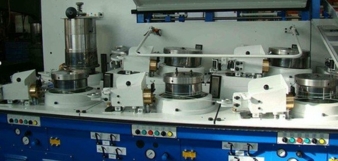
Example of special machine for fine spring wire manufacturing. © MFL Group
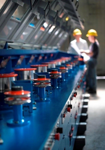
Example of long spring wire drawing m/c. © MFL Group
Due to the high tensile strength of the finish product, combined with narrow tolerances of the mechanical properties, such manufacturing had to be performed following strict guidelines.Spring wire is characterised by its elasticity, which is frequently achieved by selecting the proper raw materials alloy components (e.g., Silicium or Manganese). Typical applications are pressure springs, tension springs or torsion springs, and valve springs. All these applications have in common that the product’s elasticity is very high. This is required so that – after the load is released the spring moves back into its original position.
To fulfill the stringent requirements of spring steel wire, the production process must be set up precisely and consistent. One of the key steps for producing such demanding wire is the drawing technology. Obviously, the drawing technology applied is not the sole factor for realising the proper wire downstream. Suitable wire rod, efficient surface cleaning and/or coating, correct drawing dies, combined with the right lubricants are all important factors to success. For the calculation of the drawing sequence, the wire inlet specification determines the finish wire size, and its required final tensile strength.Using the ratio of wire tensile strength increase over the cross sectional area reduction, the correct total reduction is calculated and the corresponding wire inlet size is selected. If the finished product does not demand a narrow chemical composition, the choice of inlet wire may be adjusted to achieve the final product specification.
Once the inlet size has been selected, there are two important parameters to be defined:
– How many drafts?
– Constant or tapered reduction schedule?
While the number of drafts depends on the available equipment, the area reduction per draft should not be over 18% to 20% in average.
The individual reductions should not be constant, as this would lead to negative impacts on the wire temperatures and therefore on the quality of the finish wire. Decreasing continuously the wire reduction schedule by about 1% per draft is a commonpractice.Drawing high class spring wire at maximum speed demands an outstanding cooling system on the wire capstans: The combination of controlled/efficient water flow inside the capstans and optimised drawing capstan geometry –with regards to heat transfer and wire climbing ability on each capstan – allow consistent and productive spring steel drawing. This method has been proven and has been utilized many years on MFL and KMT equipment.
Speed synchronization between the drawing capstans is done using various methods:
– Conventional dancer system.
– Limit stroke roller/tuner roll.
– Controlled back pull without wire deviation.
All of these systems can all be electronically handled with a modern PLC-system.Thereforethe selection reflects back to the manufacturer to design the most suitable solution for his specific product.
Once the wire leaves the drawing machine, the job is not yet accomplished: Shall the wire be collected by a (drawing) coiler, a spooler or a stripper block? The first option seems critical for many high class spring wires; the second one is quite common; the third one – though appearing “old fashion” – according to some specialised producers can assure optimum wire quality. Due to constantly increasing market demand and with the goal of achieving wire production with consistent and reliable qualities,optimum internal control tools are required: the newly developed MFL IoT tool provides unlimited access to the process, knowing about OEE, energy consumption, recipe analysis, breakdowns etc. It can provide maximum transparency of the entire transformation process! A continuous relationship to the end-user, with outstanding techniques proposed is the basis for an optimum production solution for spring wire, in a tailor-made shape according to the customer’s requirements.
Mario Frigerio S.p.A.
Via del Carroccio n.8, 20123 Milan/Italy
Contact person is Carina Koch
Tel.: +49 2372 985 345
c.koch@mflgroup.com
www.mflgroup.com