28/01/2019
Measuring solutions for fibre optic manufacturing processes
Fibre optic cables make very particular demands on the in-line measuring technique. This is due to the extremely small dimensions of the fibre itself, with tolerances in the sub-micron range when drawing and coating.
© Zumbach
© Zumbach
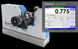
Swiss Zumbach Electronics offers measuring solutions for nearly all fibre optic manufacturing steps, such as
- Diameter, ovality, position when drawing the fibre
- When coating
- With the loose tubing process
- When extruding the external jacket
- For manufacturing tensile elements made of steel or "Kevlar" and do forth.
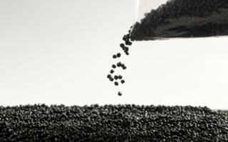
1. The start of fibre optic cable is with silica sand which is formed into what is known as a preform. This is a high quality glass tube with an almost perfect surface both inside and out and a concentricity and wall thickness as precise.
2. In manufacturing the preform, typically a lathe process is used, where precision instrumentation is required to measure the outer diameter, feeding valuable process data back to the machine to enable continuous control. This is typically completed using scanning laser dimeter gauges. As the process can encompass process temperatures in excess of 2,000°C, any instrumentation has to be carefully prepared specific to the installation.
3. The completed Preform is then mounted to a tower which acts as the extrusion process. This is known as the draw process, whereby intense heat is directed to the base of the Preform causing it to melt and form a droplet. The fibre takes its form.
4. The droplet is captured at the bottom of the drawer tower by a capstan unit, acting as a pulling station. The Preform is fed by a drive system into the heated area at the top of the drawer tower, so as to maintain a continuous droplet, and thus a continuous uniform diameter fibre.
5. Through the draw process, positioning of the preform in relation to the heating device is critical to ensure a concentric and an almost perfectly round filament. This is maintained by multiple servo drive solutions that feed the Preform through the heated area, but also simultaneously offsetting its centralised position in a 2 x axis (X and Y) format. Laser diameter gauges are essential to ensure this process is optimized, by measuring Diameter in multi-axes that can be directly related to the draw towers moving axes and simultaneously feeding back optical position related to the drawer towers true centre. The performance of a fibre is directly related to its uniformity in dimensions and cross section.
6. In the same process, multiple coats of identifying colour are applied requiring specialist curing ovens to ensure the colours are dry before any contact to further process equipment. Again specialist diameter measurement equipment are utilised to ensure uniform surface coating. Finally a surface fault device is used to capture any surface imperfections from occurrences such as missing coating, gels within the coating, bubbles, scratches and de-laminations.
7. from the capstan device. The finished fibre is wound onto drums to required lengths, which today can extend beyond 3km at a time.
8. Optical fibres are typically grouped into bundles specific to their final application, where key is to ensure no tight stranding, bending or kinking occurs risking breakage of the fundamental glass filaments that they are. Typical forms of bundled fibres are known as Ribbons, loose tubes, tight buffered fibres and Zip Twins. The number of fibres in each unit can range from a single fibre to maybe 32 or more, always considering for redundancy/future increases in needs.
9. The varying process’s to complete these differing forms of packaged fibres, include jelly filled tube extrusion, S-Z stranding, tube extrusion, ribbon colouring, over stranding with materials such as Kevlar filaments and so on.
10. Again for these multiple processes, specific instrumentation requirements exist to measure in process and offer control capabilities to maintain product parameters such as outer diameters, inner diameters, wall thickness, concentricity, fibre lengths, and surface finishes. Among the instruments are devices such as laser diameter gauges, lump and neck down surface detectors, non-contact speed and length devices, ultrasonic wall thickness devices.
The preform process in greater detail
Examples of preforms in differing methods of manufacture: The key to making superior optical fibre is combining highly purified materials with the best manufacturing process. The fibre can either be “directly drawn” or it can bedrawn from a “preform”, which is essentially a multi-layered pure ‘glass’ blank that maintains specific ratios to the final fibre.
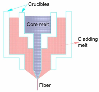
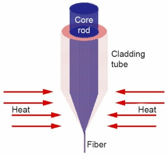
“Direct draw” is no longer used by the major fibre manufacturers; due to the high attenuation of the fibre produced by these methods (it is difficult to not introduce impurities when utilizing these manufacturing methods). It is worth a passing mention of the two main direct drawing processes: Double crucible method involves drawing the molten core glass through an inner crucible and the molten cladding glass through and outer crucible. The main advantage of this method is that infinitely long fibres can be drawn, as long as the crucibles are constantly refilled. Even Step/Graded index fibres can be drawn in this manner. Rod in tube method involves placing a rod of hard core glass inside a tube of hard cladding glass. The end of the assembly is heated and as a result the softened glass can be drawn. It is important that the two types of glass have similar softening temperatures.
In the internal deposition (IVD) method, a tube of ultrapure silica is mounted on a glass working lathe, equipped with an oxygen-hydrogen burner. The chlorides and oxygen are introduced from one end of the tube, and reacted by the heat of the burner. The resulting soots (submicron particles of silica and germanium) are deposited inside the tube down flow of the burner. As the burner passes over the deposits, they are vitrified into solid glass. The refractive index profile is built layer after layer, from the outside to the core, by varying the proportion of silicon and germanium chloride (the more germanium, the higher the refractive index). The advantages of this method are that the reaction is confined inside a tube, and vitrification is done in the same step as the deposition.
in the outside deposition (OVD) method, chemical vapours are oxidized in a flame via a process called hydrolysis. The deposition is done on the outside of a silica rod as the torch moves laterally. When deposition is complete, the rod is removed and the resulting tube is then moved to another process for collapse and vitrification. This method is claimed to result in the very best uniformity at the centre of the fibre (centre-line dip), which will become increasingly important as light sources move from LED to laser. A major cost factor in fibre optics is the need for amplifying the signal over great lengths. In the transition to high power lasers from low power LED light sources, these distances [between repeater stations] will increase. A drawback is that the higher power of the laser requires greater purity at the centreline, otherwise complications will develop.
Collapse: After the preform has been manufactured in the OVD and IVD processes, further steps are required before the preform is ready for drawing into fibre. In both cases, there is a void at the centre of the preform (much larger in the case of OVD) which requires collapsing. With OVD, vitrification is also required.
Zumbach’s role in the process
In all three processes, IVD, OVD, and VAD, it is absolutely critical to maintain dimensional specifications during the layering process (it is critical for each layer to be of specific thickness and composition). Exact ratios must be maintained so that the final drawn fibre will have the required performance characteristics.
The two primary functions that the diameter gauge provides are diameter and position. Diameter is critical to determine deposition layer thickness, while position is critical for maintaining the spacing between the tubular preform and the deposition torch, typically between 35mm and 55mm. Diameter increases with each pass (OVD), but the torch position relative to the outer surface of the preform must be constant.
It should be mentioned that, dimensionally speaking, the larger the diameter of the preform, the longer a single fibre can be drawn from it. The trade-off here is that attenuation increases with preform diameter, thus limiting fibre length. As the processes are refined to produce lower attenuation fibre, it can be reasoned that the preform diameters will increase proportionally. As an example, an 80mm diameter preform can produce one single mode fibre of 400km in length and 0.125mm in diameter.
Both IVD and OVD rely on the “fibre lathe” for preform manufacture. This lathe is essentially identical to a machinists’ lathe, with spinning chucks holding the ends of the “work piece”, in this case a quartz tube.
VAD is a special case because the deposition is done in the axially in a semi-sealed chamber (“pre atomizing spraying chamber”) on a vertical tower (these massive structures are several floors in height). This method applies all deposition layers in one pass utilizing multiple torches, each responsible for a layer (core, cladding, etc.). The preform is welded at the top and bottom to suspender rods (also quartz) which are then placed in upper/lower chucks in the tower. The preform is rotated and simultaneously is pulled between the two tower chucks to maintain desired diameter and layer thickness.
VAD requires a diameter scanner to measure through a site glass. Heat shields are recommended but not required (note that chamber temperatures reach 3,000°C). The diameter gauge must be capable of reading accurate diameter along the preform, and also finding the transition point between the quartz suspender rods and the actual preform (identified by diameter variation).
Fibre drawing in further detail
With the fabrication of the preform, the manufacturing moves on to drawing the optical glass fibre from the preform. This is typically accomplished by placing the preform at the top of a drawing tower and utilizing heat to soften the glass so that it begins to liquify. At this point a ball of molten glass forms at the bottom of the preform which is then routed through the machinery to a take up reel. Once specifications have been met, the end (glass ball) is removed and the remaining fibre is put onto reels. The various stages of this process are explained below.
There are seemingly endless permutations on types and brands of fibre produced by these methods, but all fibre can be grouped into two broad categories, Single mode fibre and multi-mode fibre. The word mode describes an independent light path through a fibre. Therefore, “single mode” refers to fibres that allow only one path, and “multi-mode” refers to fibres that allow many. Typically, the single mode fibre is used for long distance transmissions (km) and the multi-mode is used for shorter distances (2000m or less), although these rules are not written in stone.
All fibre includes a core and a cladding layer, the dimensions of which are determined during the preform stage. The outer diameter of both types of drawn fibre is 125µm, consisting of the core, which carries the light waves, and the cladding. The protective UV coating(s) vary widely but typically bring the final diameter up to between 250µm and 900µm.
Typically single mode fibre typically has a core diameter of 8µm, requiring a cladding layer of approximately (125 – 8/2) 58.5µm thickness. Multi-mode fibre cores can be, literally, any dimension, but typical core diameters are 50µm and 62.5µm (for cladding thicknesses of 37.5µm and 31.3µm, respectively).
The larger core of the multi-mode fibre allows for many more pathways (modes) for the light to travel. However, the trade-off is higher attenuation of the light wave (light travels greater distances per unit length of the fibre). The single mode restricts the number of pathways (modes) to only one, but results in much greater transmission distances between regeneration of the signal.
A sub-step of the fibre drawing process is colourization of the fibre by application of UV cured inks. This allows each fibre to be identified in terms of type, size, and performance characteristics simply by its colour.
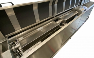
Examples show a fibre drawer tower, loose tube cables within a multi-core fibre conduit that allows for blowing (installing in the field) further fibre cables. This is made with the assistance of a compressed air source to aid in carrying the fibre down the already installed conduit.
Bruno Mühlheim ist technical editor in Oprund/Switzerland
Interwire 2019, booth 1341
Zumbach Electronic AG
2552 Orpund/Switzerland
Contact person is Mr. Daniel Frankum
Tel.: +41 32 3560400